
Alienware 15″ R4 2018 Teardown & Disassembly Guide – Model P69F002
OVERVIEW:
In this teardown tutorial, we’ll walk you through the complete disassembly of an Alienware R4 15-inch (2018 model). Whether you’re replacing internal components or simply want to understand how your machine is built, this guide has you covered. Each step is clearly broken down to help even first-time repairers follow along. No extra info—just what’s shown in the video. Grab your tools and let’s get started. This is a full teardown, so you’ll gain access to the motherboard, battery, SSD, fans, and even the LCD panel.
See the official Alienware specs for this model
REPAIR TIME & SKILL LEVEL:
This repair is estimated to take about 1.5 to 2 hours to complete and is of ADVANCED difficulty, requiring careful attention to component removal and multiple internal cable disconnections.

STEPS:
Tools You Need
For this repair, you’ll need a Phillips screwdriver, a plastic pry tool for safely opening the casing and lifting internal components, and ESD protection like an anti-static wrist strap. You may also need tweezers for small connectors and patience for dealing with adhesive and tightly secured parts.
-
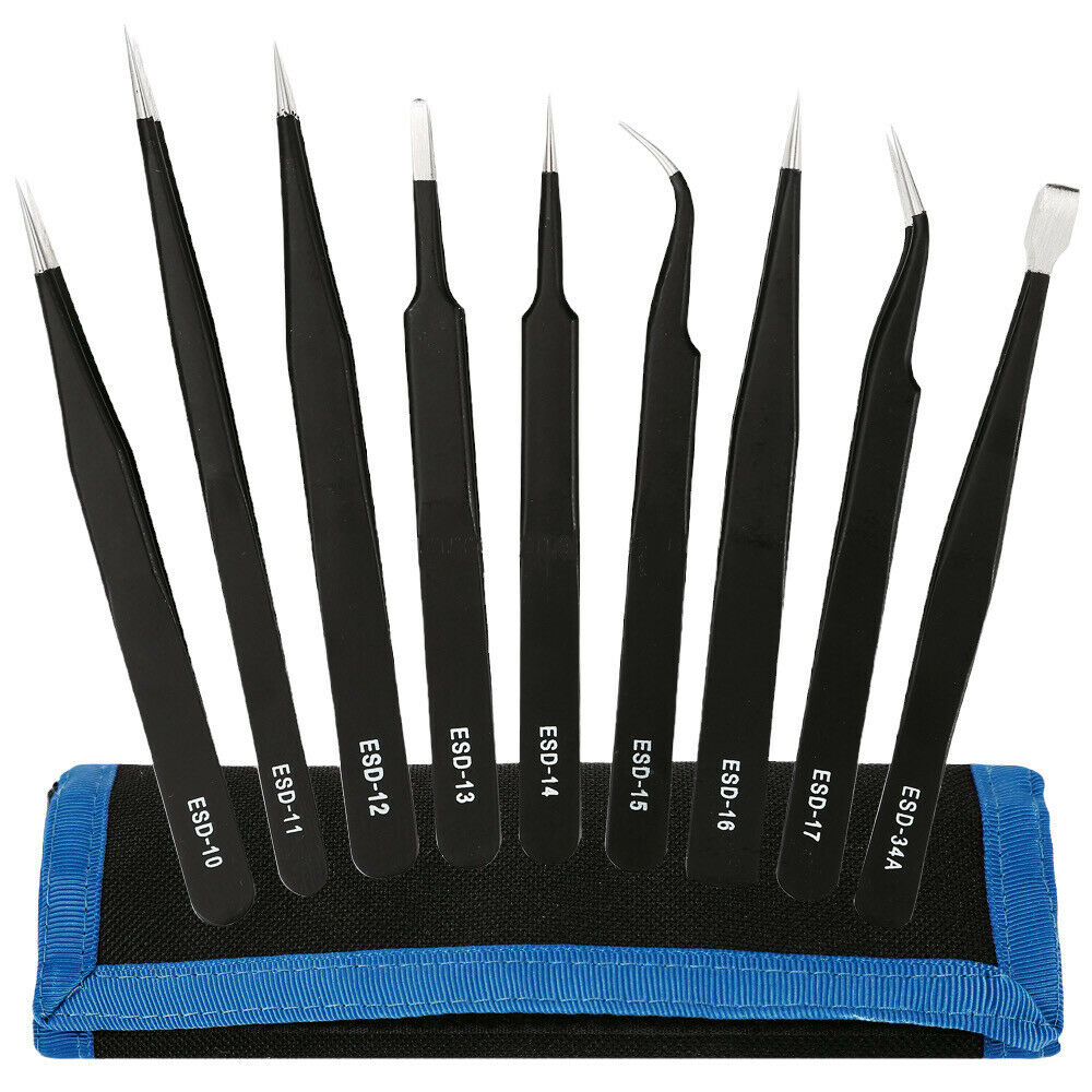
Kingsdun ESD-9 9pcs Anti-static Stainless Steel Tweezers Set for Electronic Phone Repair Tools
-26% $14.00Was:$19.00 -

GD900 Thermal Paste High Performance Grease, 1 Gram Syringe
$5.00 -

140 in 1 Steel Bit Precision Magnetic Screwdriver Tool Set with Case for Phone PC Electronics
$25.00 -
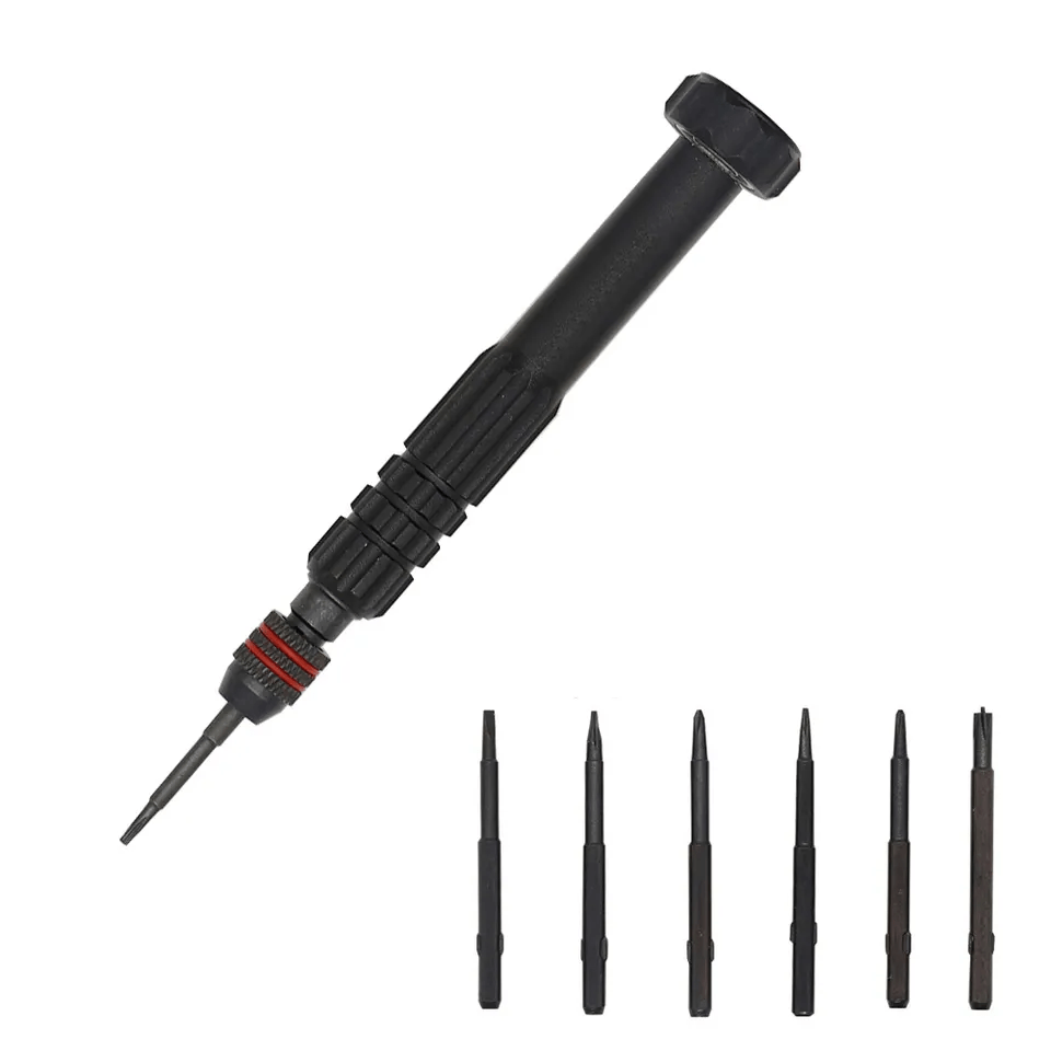
6 in 1 Steel Bit Precision Magnetic Screwdriver Tool Set with Case for Phone PC Electronics
$8.00 -
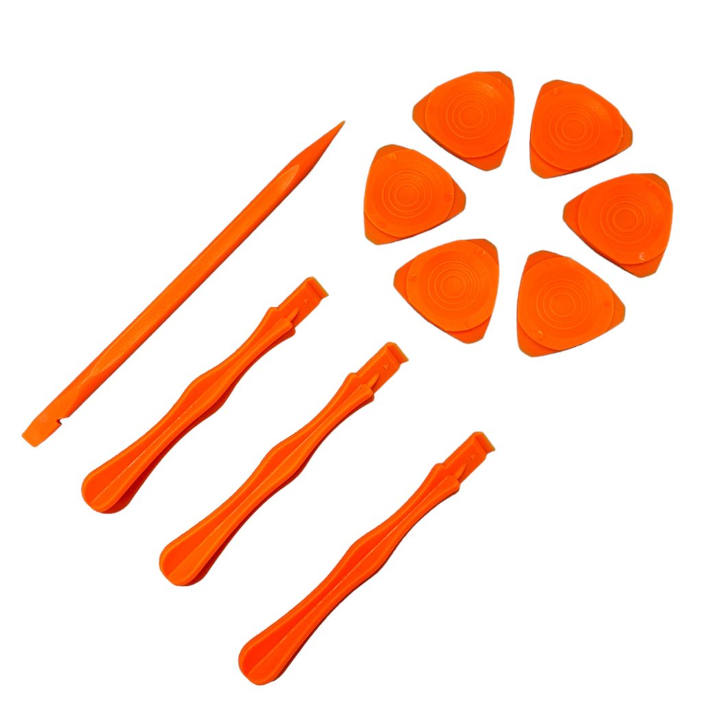
Professional Spudger Kit, 10 in 1, Anti Static Pry Tools For Electronics and Display Repair
$7.00
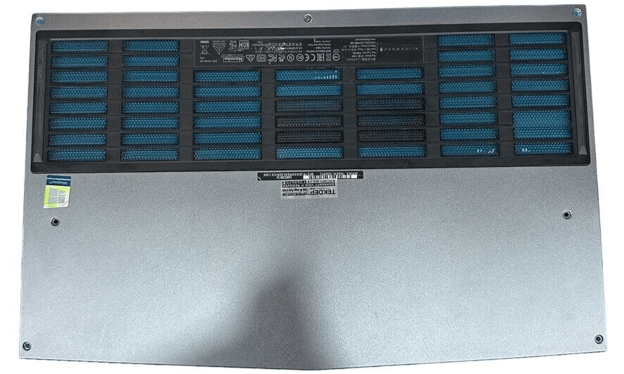
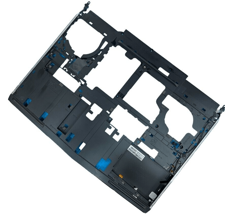
Remove the Bottom Case
- Ensure the laptop is completely powered off before beginning.
- Use a Phillips screwdriver to remove all bottom screws. Note that the center-rear screw is a captive screw and will not fully detach.
- Slide the case slightly toward yourself and pull up gently to remove the bottom shell.

-
P69F002 Original Bottom Case Cover for 2018 Dell Alienware R4 15-inch
-8% $119.00Was:$129.00
Remove Rear Housing Screws
- Flip the laptop over to access the back.
- Remove the two screws located at the rear edge of the laptop.
- These screws help secure the rear housing cover.

Detach Rear Housing
- Using a plastic pry tool, unlatch and remove the rear housing by releasing clips located on the back panel.
- Work slowly and carefully to avoid damaging the clips.
- Set the housing aside once it’s free.

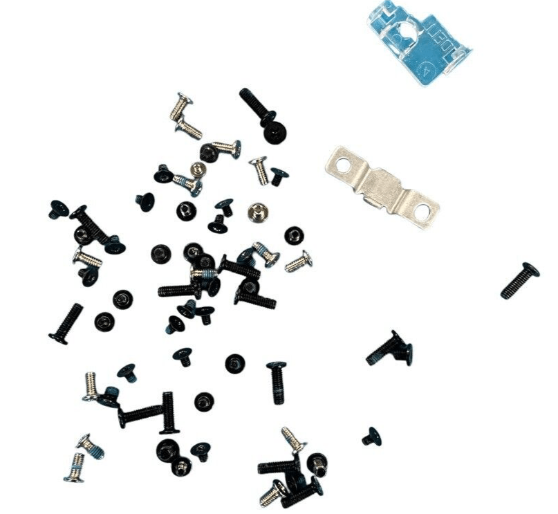
Remove Internal Screws
- Inside the exposed chassis, locate and remove 12 internal screws to proceed further.
- These screws hold down multiple internal structures, so be organized while removing them.
- Keep track of screw locations for easier reassembly.

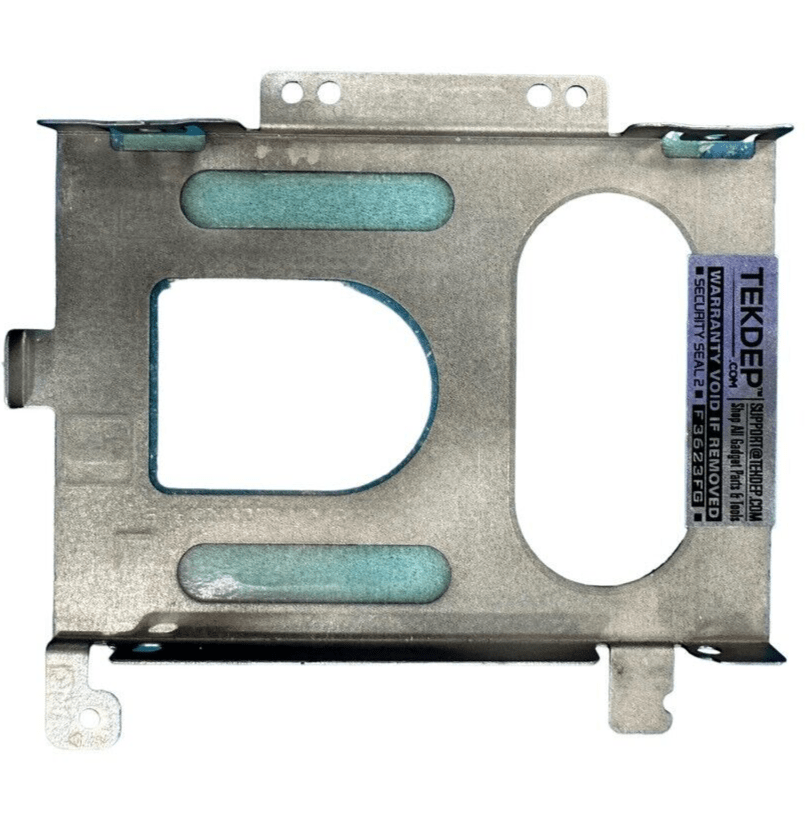
Detach 2.5-Inch Drive Tray
- Locate the 2.5-inch hard drive tray and remove its four mounting screws.
- Note that one of the screws may be missing—this is common in previously serviced units.
- Gently lift the drive tray out of the chassis.

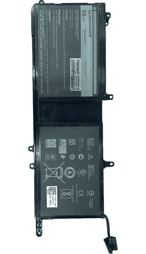
Disconnect the Battery
- Carefully unplug the battery connector from the motherboard.
- Bend the connector cable slightly away from the socket to prevent accidental reconnection or ESD issues.

-
P69F002 Original Battery Model 9NJM1 for 2018 Dell Alienware R4 15″
-74% $31.34Was:$119.01
Remove M.2 SSD
- Locate the M.2 SSD and remove the single screw securing it.
- Slide the drive out gently by pulling it toward yourself.
- Set the drive aside on a safe, static-free surface.
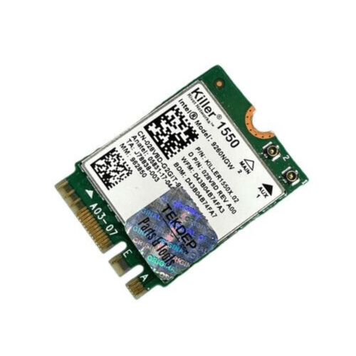
Uncover Wi-Fi Card
- Locate the Wi-Fi card hidden under a plastic shield or cover.
- Gently remove the shield to reveal the Wi-Fi card.
- Do this step before removing the internal frame (skeleton) to avoid motherboard or card damage.
-
P69F002 Original WiFi Bluetooth Card for 2018 Dell Alienware R4 15-inch
-81% $17.09Was:$89.01
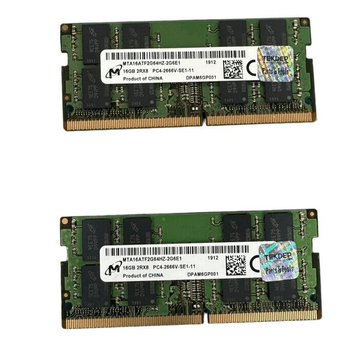
Remove RAM Modules
- Identify the RAM slots and use your fingers to push outward on both metal retention clips.
- The RAM sticks will pop up once freed.
- Gently remove each stick from its slot.
Unplug Side LED Connectors
- Locate the LED strip cables on both the left and right sides of the chassis.
- Disconnect each from the motherboard.
- Gently remove the wires from their hold-down clips on the chassis frame.

Pry Open the Skeleton Frame
- Stand the laptop on its side and insert your pry tool into the seam between the skeleton and the top case.
- Carefully work your way around the edge to separate the frame.
- Remove the skeleton and set it aside.

Remove Battery Pack
- Locate the remaining battery mounting screw and remove it.
- Lift the battery unit gently and set it aside.

Disconnect Ribbon Cables
- Open the various ribbon cable connections across the motherboard.
- Be careful with latches—some lift up, others pull back.
- Don’t forget to disconnect the BIOS speaker cable during this process.

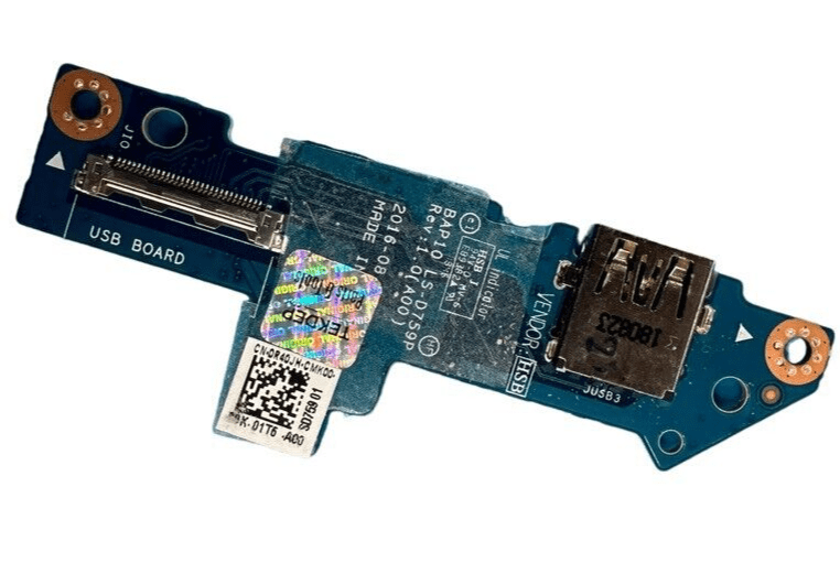
Remove USB Daughterboard Cable
- Locate the cable running beneath the motherboard that connects to the USB daughterboard.
- Unplug the cable carefully.
- Remove screws securing the USB daughterboard and lift the board out.

-
P69F002 Original USB Daughter Board with Cable for 2018 Dell Alienware R4 15-inch
-90% $7.59Was:$79.01
Disconnect Front Speaker Wire
- Unplug the front speaker wire that runs across the lower portion of the unit.
- Gently pull the connector without yanking on the wires.


Unscrew the CPU and GPU Fans
- Locate the screws securing the two cooling fans.
- Remove all screws from both CPU and GPU fans.


Lift the Motherboard Carefully
- Gently tilt the motherboard upward.
- Do not remove it fully yet—cables remain attached underneath.
- Avoid lifting too far to prevent damaging ribbon cables.
-
P69F002 Original Motherboard DDR51 LA-F551P for 2018 Dell Alienware R4 15-inch
-8% $599.00Was:$649.00

Disconnect Cooling and Display Cables
- Unplug the fan connectors on each side of the board.
- At the bottom edge, disconnect all remaining cables, including the LCD cable.
- The far-right connector uses a spring retention bar—take extra care here.

Flip and Remove Heat Sink
- With cables detached, flip the motherboard to access the underside.
- Unscrew the heat sink retention screws.
- Gently lift the heat sink—expect resistance due to thermal paste adhesion.
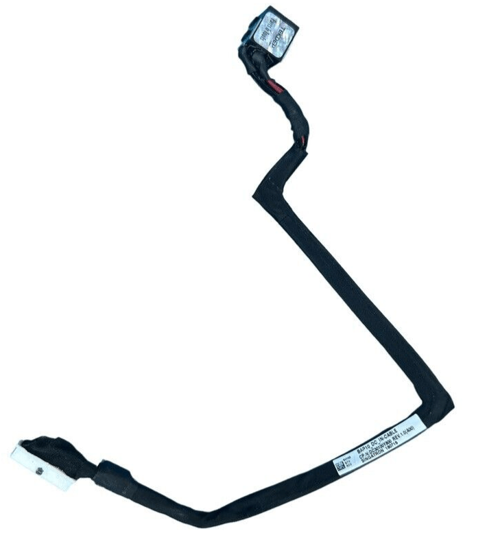
Remove Charging Port Assembly
- Locate the charging port cable.
- Use your pry tool to lift it free, working through adhesive slowly.
- Remove both the cable and port with care.

Remove Mouse Buttons
- Unscrew the mouse button mounting screws.
- Disconnect the small ribbon cable attached to them.
- Lift the button assembly out of the chassis.

Lift Back Plate
- Locate the rear metal plate.
- Use your pry tool to lift the plate from its position.
- Remove it completely to expose the keyboard.

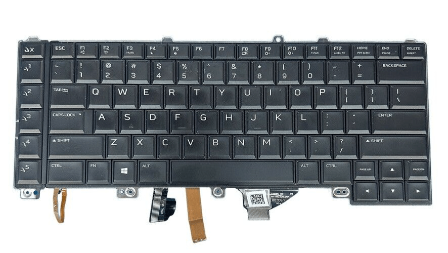
Detach Keyboard
- Pry up on the keyboard edges gently.
- Once loose, slide it toward yourself to fully remove it from the case.
-
P69F002 Original Keyboard for 2018 Dell Alienware R4 15-inch
-80% $23.74Was:$119.01
Remove LCD and Wi-Fi Assembly
- Unscrew the six screws securing the LCD panel and Wi-Fi antenna assembly.
- Carefully lift the entire assembly up and off the chassis.
- Set it aside safely—this completes the teardown.
CONCLUSION:
This teardown of the Alienware R4 15″ (2018) walks you through each step to fully disassemble the device. With careful handling and the right tools, you can safely access and replace internal components. From the keyboard and battery to the fans and display, everything is reachable with patience. This guide aims to make each step easier to follow with a clear structure. Always remember to organize your screws and take static safety precautions when handling internals.


VIDEO TUTORIAL:
Looking for a more in-depth tutorial? Check out our complete teardown video for a detailed step-by-step walkthrough.
MAIL-IN REPAIR SERVICE:
We offer professional screen replacement services. If you’re unsure about doing this repair yourself, send your device to our expert technicians for fast and reliable repair.
SHOP PARTS:

Alienware R4 15 2018
Restore your Alienware 15 R4 to peak performance with our genuine OEM parts. From vibrant displays to responsive keyboards, find everything to keep your machine game-ready.
SHOP TOOLS:
Using precision tools ensures a safe and efficient repair. Always use the right tools to prevent damage to delicate components. Visit our store for curated tools made for tech repairs.

REPAIR TOOLS
Discover an extensive range of tools, including screwdrivers, tweezers, pry tools, and more, essential for all your repair and maintenance needs.
HAVE QUESTIONS?
If you have any questions, leave them in the comments below. Our community and team will be happy to help!
- Phone: 818-456-4479
- Email: [email protected]

YOUR EXPERIENCE MATTERS:

Microsoft Surface Laptop Studio Battery Replacement: Beginner’s Guide
The Microsoft Surface Laptop Studio is notoriously complex, but replacing its battery is surprisingly simple. Follow our step-by-step beginner's guide to safely remove the hidden fasteners and swap the backplate-mounted battery.

A3112 MacBook Pro M4 Teardown: Logic Board Extraction and Parts Pairing Rules
The 14-inch MacBook Pro M4 (A3112) brings powerful Apple Intelligence, but introduces a cryptographic minefield for DIY repair. Learn how to extract the logic board and bypass parts pairing restrictions.

MacBook Pro A1706 Teardown & Flexgate Diagnostic Guide
The MacBook Pro A1706 introduced the Touch Bar and a host of internal complexities. Our expert teardown guide breaks down the glued battery challenge, logic board extraction, and the infamous Flexgate issue.

Official TEKDEP Tutorials
Subscribe for expert tutorials, pro tech tips, and teardowns.
