Model: A3112 (MacBook Pro 14-inch, M4, 2024) | Level: Advanced
The Apple MacBook Pro 14-inch M4 (Model A3112) represents the dawn of the Apple Intelligence era. Released in late 2024, the A3112 serves as the baseline professional machine, finally offering 16GB of unified memory as standard, a 10-core GPU, and an upgraded three-port Thunderbolt 4 layout to match its Pro and Max siblings.
However, beneath its Space Black and Silver aluminum exterior lies a highly integrated engineering marvel that presents unprecedented challenges for independent repair. Apple has doubled down on cryptographic parts pairing. Successfully repairing an A3112 in 2026 requires much more than simply turning screws; it requires a deep understanding of the macOS Repair Assistant, Lid Angle Sensor calibration, and navigating hidden fasteners (what the industry affectionately calls “weird nubbins”).
In this comprehensive TEKDEP master guide, we perform a complete frame-off teardown of the A3112. Whether you are replacing a burnt-out USB-C board, upgrading a damaged display assembly, or performing a full 820-03129 logic board extraction, this is your definitive blueprint.
The Technical Reality: The Cryptographic Minefield
Before we breach the chassis, you must understand the new software hurdles inherent to the M4 architecture.
1. Parts Pairing & The macOS Repair Assistant
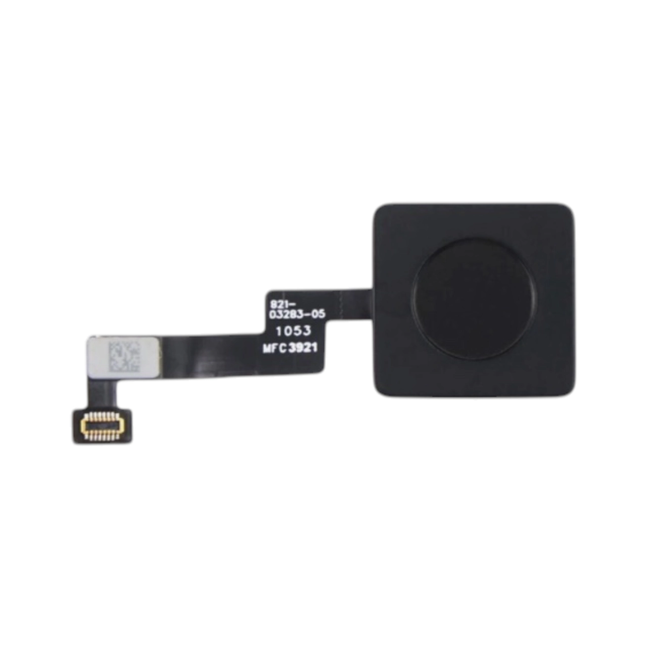
Starting with macOS Sonoma and heavily enforced in macOS Tahoe/Sequoia, Apple serializes critical hardware components to the M4 SoC’s Secure Enclave. If you replace the Display Assembly, Touch ID Sensor, or Lid Angle (Sleep) Sensor with another genuine Apple part, the Mac will detect a hardware mismatch. This can result in visual artifacts, disabled True Tone, unresponsive fingerprint reading, and severe sleep/wake malfunctions. To finalize these repairs, you must run the macOS Repair Assistant with an active internet connection to securely verify the components with Apple’s servers.
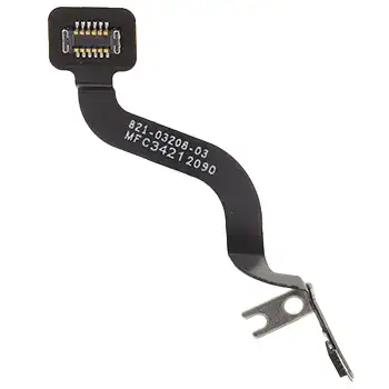
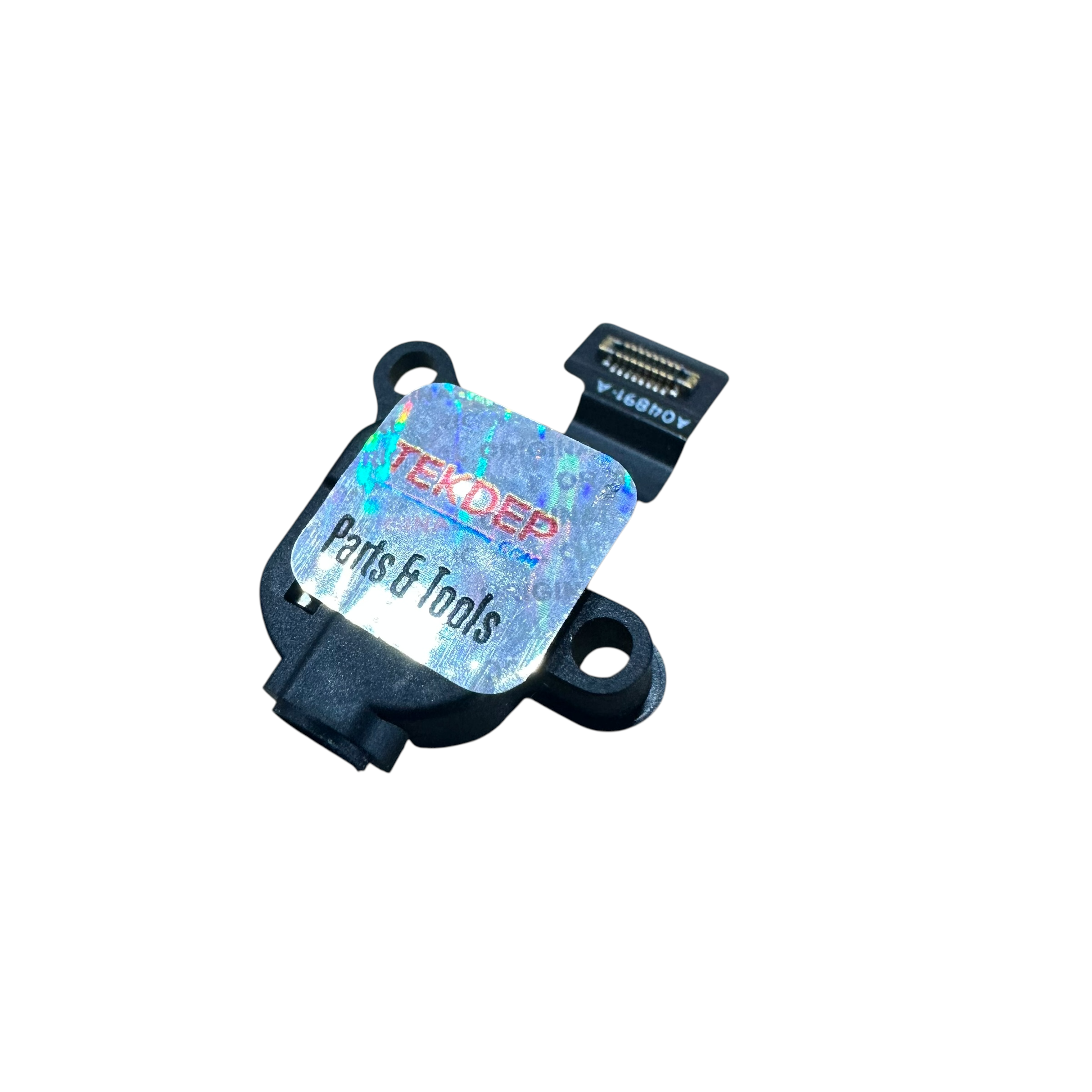
2. The Lid Angle Sensor Calibration
The Lid Angle Sensor detects the exact angle of your display, controlling sleep states and screen dimming. If you replace the screen or logic board, the sensor loses calibration. While the Apple Repair Assistant can sometimes resolve this, many technicians rely on physical third-party calibrators, like the NerdTool 1 Lid Sensor Calibrator, to force the hardware handshake and bypass glitching screens.
3. The Trackpad Anomaly
Just like the M2 and M3 generations, the A3112 features a frustrating design quirk: you must remove the trackpad to safely extract the battery. The primary battery pull tabs and flex cables are routed directly beneath the Force Touch assembly.
TekDep Expert Insight: “The A3112 bridges the gap between consumer and pro. With 120 GB/s memory bandwidth and hardware-accelerated ray tracing, it is a powerhouse. But for repairability, it is a minefield. The introduction of ‘weird nubbins’ to hide logic board screws and the microscopic T1 screws on the MagSafe port show that Apple continues to prioritize internal density over easy disassembly.”
⚠️ Critical Safety & Professional Tooling
The A3112 requires extreme precision. Stripping a logic board screw or tearing a serialized flex cable will instantly force a full top-case replacement.
Required Tooling for the A3112:
- P5 Pentalobe Screwdriver: For the external backplate.
- Torx T1, T3, T5, and T8 Screwdrivers: The core tools for the logic board, trackpad, and modular I/O ports. (Note: The T1 is incredibly rare but required for the MagSafe port).
- Nylon Spudger & Anti-Static Pry Tools: Essential for safely disconnecting Lego-style and ZIF flex cables.
- NerdTool 1 Calibrator (Optional): Highly recommended for third-party screen or lid angle sensor swaps.
Get the Professional Grade Tools Used by Our Techs:


Phase 1: Taking Off the Backplate
As Nicholas notes in the video tutorial, the first step to any MacBook repair is breaching the external chassis safely without bending the aluminum hooks.
Step 1: The 1.2 Pentalobe Screws
Turn the M4 MacBook Pro face down. Using your 1.2 Pentalobe screwdriver, remove the eight screws securing the backplate: four on the top edge near the hinge, and four on the bottom edge.

Step 2: Clearing the Hinges (The Push/Pull Method)
Once the screws are out, the plate will not simply lift off. Take your plastic pry tool and insert it into both sides of the chassis to clear up the two internal clips holding it down. Once the sides pop free, do not pull straight up. Instead, use this specific technique: Push with your bottom hand and pull with your top hand on the backplate. It should pop right out, disengaging the heavy-duty top hooks cleanly.


Phase 2: Disconnecting the Battery & Trackpad Flex
With the internals exposed, you are looking at a live logic board. Our immediate priority is neutralizing the 70Wh battery. However, Apple has engineered a hurdle: the battery flex cable is hidden underneath the trackpad cable.
Step 1: Moving the Trackpad Cable Grab your T3 screwdriver and take off the two screws holding down the trackpad flex cable bracket in the middle of the board. Take your pry tool, go right underneath the trackpad connector, and lift it up. Gently pull back the mild adhesive securing the trackpad flex cable to the battery to expose the power connections underneath.


Step 2: Neutralizing the Battery (The Pancake Screw) Now that the battery flex cable is exposed:
- Get under the top battery data clip with your pry tool and pull it out, followed by the bottom data cable.
- Use a T5 screwdriver to remove the large “pancake” screw holding down the main battery terminal.
- Flip the metal battery tab up to physically break the connection.
- Get under the top battery data clip with your pry tool and pull it out, followed by the bottom data cable.
- Use a T5 screwdriver to remove the large “pancake” screw holding down the main battery terminal.
- Flip the metal battery tab up to physically break the connection.

Step 3: The 10-Second Capacitor Discharge Disconnecting the battery is not enough. Open up your laptop and hold down the power button for about 10 seconds. This will discharge the rest of the logic board capacitors, making the computer electrically inert and safe to work on.


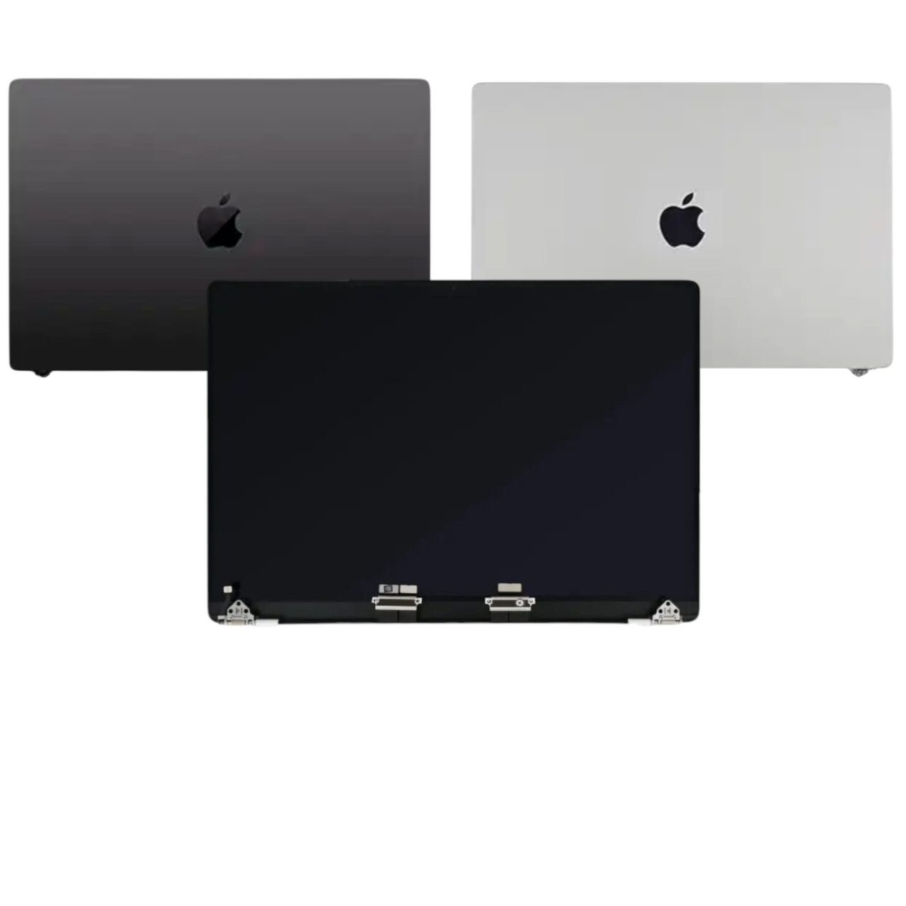
Phase 3: Wi-Fi Antenna & Retina Display Removal
Before we tackle the logic board, we must separate the top case from the display assembly. This phase involves a massive variety of microscopic screws.
Step 1: Clearing the Display Cowlings
You will be working with a mix of T5, T3, and Pentalobe screws.
- T5 Screws: Remove the screws securing the two outer hinges, the side screws, and the four T5s in the middle.
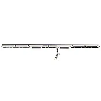
- T3 Screws: Remove the screws holding down the protective flex cable covers, the Wi-Fi and Bluetooth antennas, and the two screws on the Lid Angle (Sleep) sensor.
- Pentalobe Screws: Remove the tiny pentalobes clustered along the very top edge of the antenna bar.

Step 2: Disconnecting the Cables
Take your pry tool and carefully undo the display, camera, Wi-Fi/Bluetooth, and sleep sensor connections. Once disconnected, gently pull the cables off their adhesive pads. Warning: Ensure these cables are not creased or bent, or you will permanently damage the Liquid Retina display. Remove the Wi-Fi/Bluetooth antenna bar entirely.


Step 3: Separating the Chassis
Switch to your T8 Torx driver and undo the large hinge screws on both sides. Before opening the computer, ensure all flex cables are pushed back safely. Open the computer, hold down the bottom side to extend the hinges, and the top case should safely disconnect from the LCD. Move the LCD safely aside.


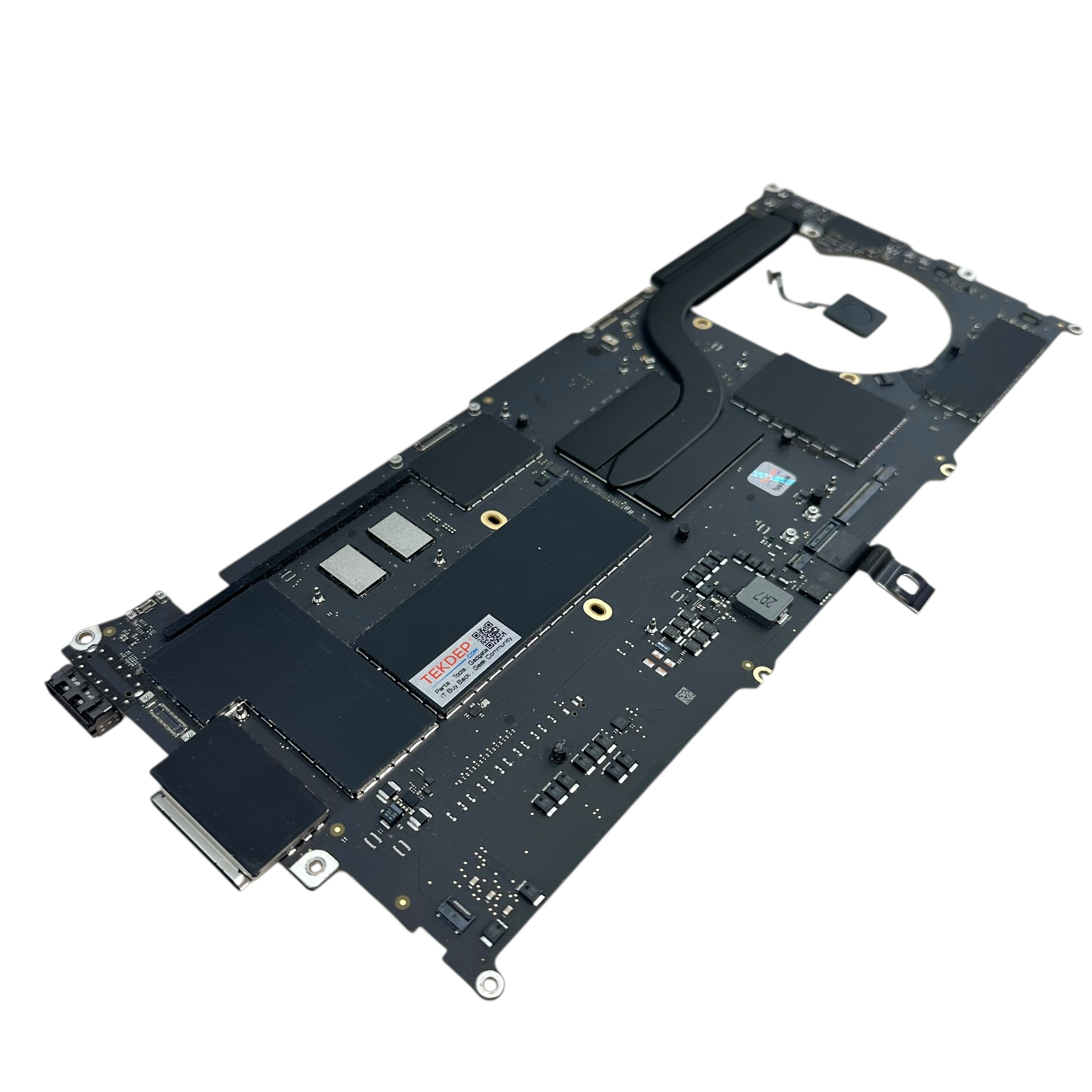
Phase 4: The 820-03129 Logic Board Extraction
To repair a broken charging port, an audio jack, or a degraded fan, the logic board must come out.
Step 1: Disconnecting Peripherals (T3)
Working left to right, use your T3 screwdriver to remove the protective cowlings over the peripheral cables. Then, use your spudger to disconnect:
- Touch ID sensor (has adhesive, go slow)
- Left side USB-C Thunderbolt
- MagSafe 3 charging connector
- Two right-side USB-C Thunderbolt ports
- Headphone/audio jack
- Left & Right speakers
- Keyboard / Top case connections
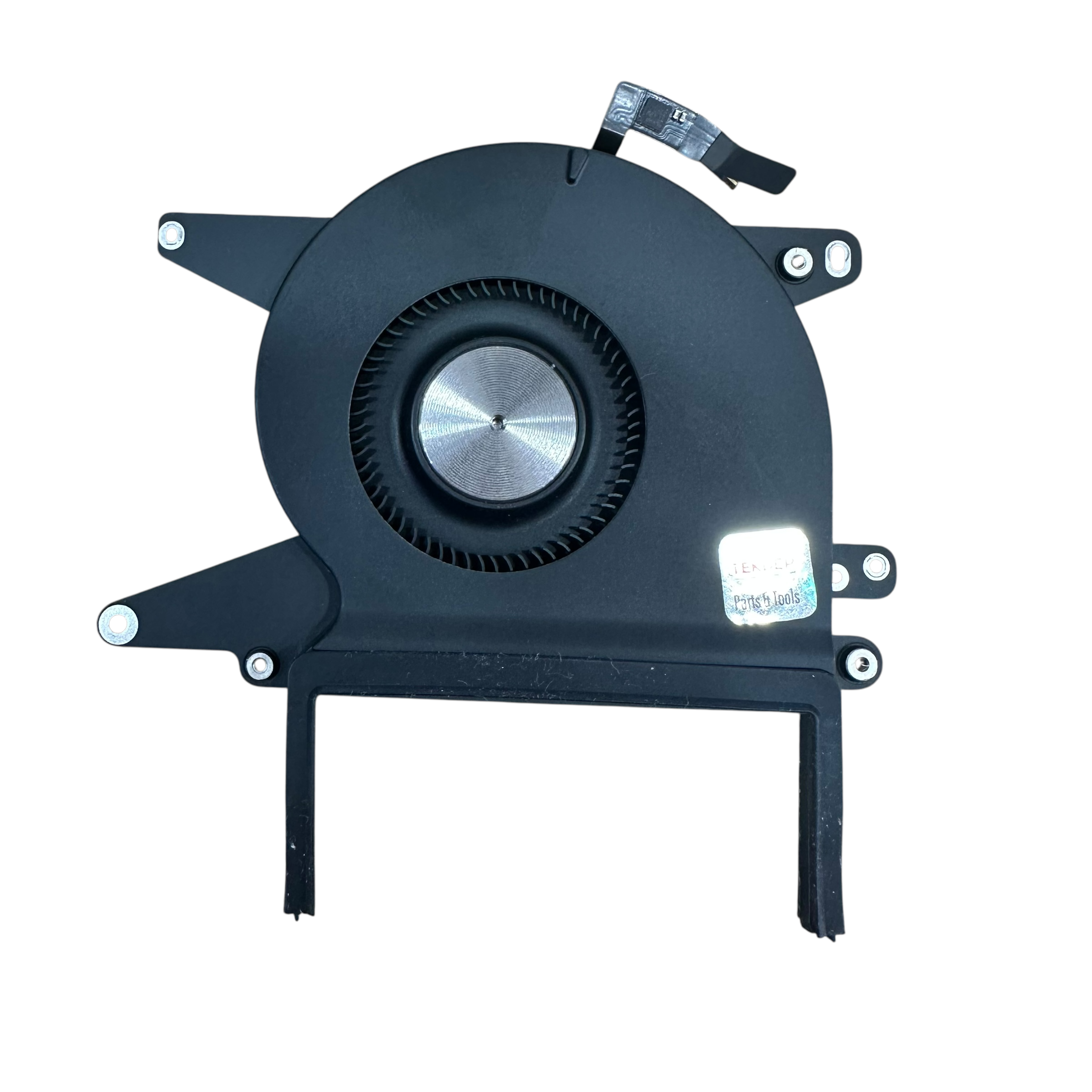
- Cooling Fan (has adhesive under the flex, lift carefully)

Step 2: Logic Board Screws (T7 & T5)
The logic board is secured by a specific screw layout. First, grab your T7 screwdriver. All of the large silver standoffs anchoring the heat sink are T7. Next, swap back to your T5 driver. Remove the logic board screws around the perimeter. Pay attention to the bottom edge: there are four T5s (the two in the middle are smaller, and the two outside corners look like pancake screws).

Step 3: Angled Extraction
The logic board is a bit tricky because the HDMI port sits behind a lip in the aluminum chassis. Remove the protective fan adhesive. Lift the logic board up gently by the right side. Once it reaches a 90-degree angle, pull forward to slide the HDMI port out of the chassis and remove the board completely.

🛑 Intimidated by ZIF Cables and Logic Boards? The M4 MacBook Pro is a minefield of fragile ZIF connectors and software locks. One ripped cable or stripped screw can cost you over $1,000 in replacement parts.
Let the TEKDEP experts handle the heavy lifting. We specialize in M4 component-level repair and macOS parts pairing. 👉 Start Your Worldwide Mail-In Repair Here
Phase 5: Touch ID Transfer & High-Wear Peripherals
With the logic board out, we can access the modular components and address the Touch ID serialization.
Step 1: Transferring the Touch ID Sensor
If you are replacing your logic board, you must transfer the original Touch ID sensor to the new board, or fingerprint reading will permanently fail due to Apple’s cryptographic locks. Use a pry tool to gently pull up the adhesive holding the cable to the chassis notch. Fold the left hinge up. Remove the T3 screws on the protective case (unscrew the four small corners first, then the two bigger middle ones). Hold up your top case, and the Touch ID sensor will drop right out.

Step 2: USB-C and Audio Jack (T5)
The dual USB-C p orts and the audio jack are highly modular. They are held in by standard T5 screws. If one suffers liquid damage, simply unscrew the two T5s and swap the board.

Step 3: The MagSafe 3 Port (Hidden T1 Screws)
Replacing the MagSafe 3 port is a bit different. It has two standard T5 screws, but inside the two little recessed pockets, there are incredibly tiny T1 Torx screws. You must have a micro-T1 driver to extract this port.

Step 4: The Cooling Fan
Fans degrade naturally over time. The A3112 fan is secured by one T3 screw and one T5 screw. Simply remove them and lift the fan out.


Phase 6: Trackpad Assembly Extraction
The trackpad is actually the easiest component to repair once the computer is open, as it only requires disconnecting the battery and the trackpad cable.
Step 1: Removing Trackpad Screws
With the trackpad flex cable already disconnected from Phase 2, use your T5 driver to remove all the screws surrounding the trackpad bracket on the top case.

Step 2: Dropping the Trackpad
Pick up your top case (or open it to a 45-degree angle if the display is still attached) and the trackpad will drop out from the bottom.
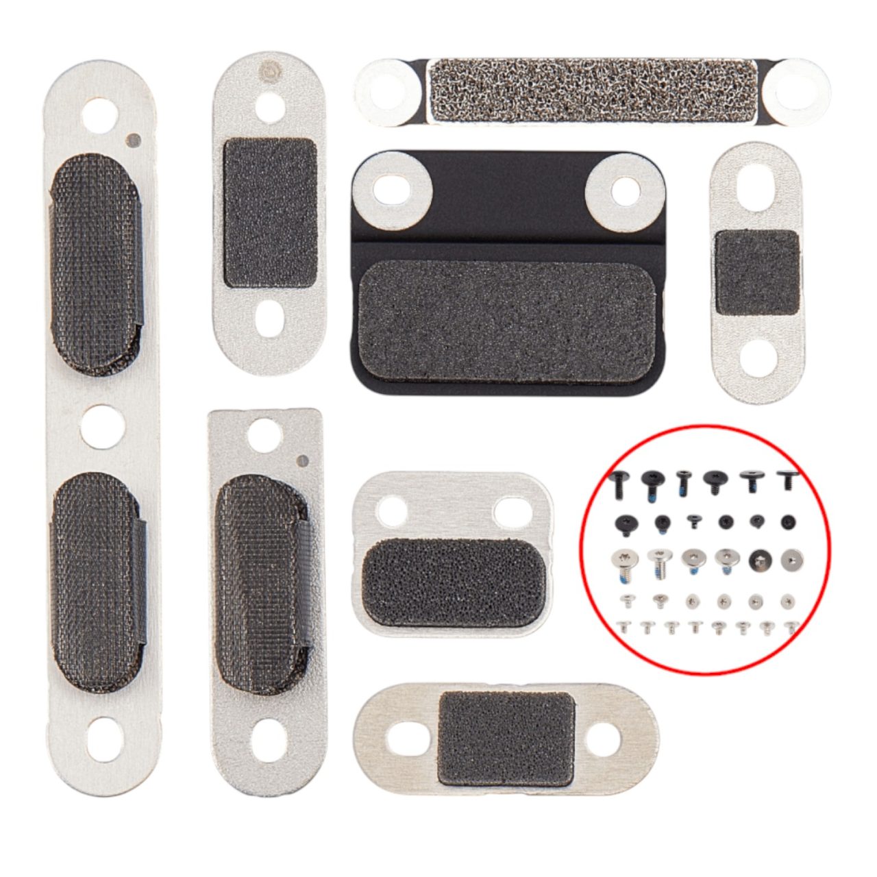
Step 3: The Haptic Washers
On the bottom of the trackpad, there are little washers that go in between the screw areas. These are critical—they provide the “taptic feedback” (the physical click you feel). You must transfer these tiny washers onto your new replacement trackpad.

Conclusion: Reassembly & Parts Pairing Rules
That is the full teardown and replacement guide for the Apple MacBook Pro 14-inch A3112 (2024 M4).
Reassembly is the exact reverse of this process. However, if you replaced the Logic Board, Display Assembly, or Lid Angle (Sleep) Sensor, you will face one final software hurdle: macOS Parts Pairing.
Apple utilizes strict cryptographic parts pairing on the M4 series. If you replace the screen without calibrating it, the logic board will fail to verify the hardware, leading to sleep issues, visual artifacts, and wireless connectivity drops. You must boot the MacBook into macOS Tahoe (or newer), connect to Wi-Fi, and navigate to System Settings > General > About > Repair Assistant to sync the new hardware to the M4’s Secure Enclave. If the software assistant fails, hardware tools like the NerdTool 1 must be used to force the calibration.
If anything in this teardown was a little interesting and you need a bit of clarification, just go ahead and leave us a comment below. We have dedicated videos for specific sub-repairs (like A2442/A3112 keyboard replacements) linked on our channel.
TEKDEP is your professional safety net. Our cleanroom-equipped lab specializes in advanced micro-soldering, OEM parts sourcing, and strict macOS Repair Assistant calibration for the entire Apple Silicon lineup.
👉 Start Your Worldwide Mail-In Repair Here
Frequently Asked Questions (FAQ)
Why do I have visual artifacts or Wi-Fi drops after replacing a MacBook Pro M4 screen?
Apple utilizes strict cryptographic parts pairing on the M4 series. If you replace the screen or lid angle sensor without running the macOS Repair Assistant or using a calibration tool like the NerdTool 1, the logic board will fail to properly verify the hardware, leading to sleep issues, visual artifacts, and wireless connectivity drops.
How do I disconnect the battery on the M4 MacBook Pro?
As shown in Phase 2 of our teardown, the battery flex cable and T5 pancake screw are hidden underneath the trackpad flex cable. You must first remove the trackpad bracket with a T3 driver, peel back the trackpad cable, and then you can access the battery terminal to disconnect the power.
Can I upgrade the base M4 MacBook Pro (A3112) RAM to 32GB?
No. The base M4 MacBook Pro comes standard with 16GB or 24GB of unified LPDDR5x memory soldered directly to the M4 SoC package on the 820-03129 logic board. It cannot be upgraded after purchase.
🛑 IMPORTANT: SAFETY & LIABILITY DISCLAIMER TEKDEP®️ TEKDEP.com assumes no liability for property damage or injury incurred as a result of any information in this blog post or associated videos. Dealing with internal computer components, specifically glued Lithium-Ion Polymer batteries, carries inherent risks including fire, toxic gas exposure, and irreversible device failure. Any injury, damage, or loss from improper use of tools, mishandling of components, or misinterpretation of this information is the sole responsibility of the user. Perform repairs at your own risk. If you are unsure of your capabilities, please utilize our professional Mail-In Repair Service.

Microsoft Surface Laptop Studio Battery Replacement: Beginner’s Guide
The Microsoft Surface Laptop Studio is notoriously complex, but replacing its battery is surprisingly simple. Follow our step-by-step beginner's guide to safely remove the hidden fasteners and swap the backplate-mounted battery.

MacBook Pro A1706 Teardown & Flexgate Diagnostic Guide
The MacBook Pro A1706 introduced the Touch Bar and a host of internal complexities. Our expert teardown guide breaks down the glued battery challenge, logic board extraction, and the infamous Flexgate issue.

iPhone 15 Plus (A2847) Battery Replacement & BMS Transfer Guide
Is your iPhone 15 Plus battery draining fast or swelling? Our expert 2,000-word teardown guide covers the complete A2847 rear-glass entry, capacitor discharge rules, and advanced BMS serialization transfer.

Official TEKDEP Tutorials
Subscribe for expert tutorials, pro tech tips, and teardowns.
