




























Model: A1706 (MacBook Pro 13-inch, Late 2016 – Mid 2017) | Level: Advanced
The Apple MacBook Pro A1706 (Late 2016 to Mid 2017) marked a controversial turning point in Apple’s design philosophy. It introduced the world to the OLED Touch Bar, replaced all legacy ports with USB-C/Thunderbolt 3, and debuted a hyper-integrated internal layout where modularity was sacrificed for thinness.
For technicians and DIY enthusiasts, the A1706 presents a formidable challenge. From heavily glued batteries that resist extraction to the notorious “Flexgate” display issue, navigating the internal components of this machine requires precision, patience, and the right tools.
In this definitive TEKDEP master guide, we perform a complete, screw-by-screw teardown of the A1706. We will walk you through the safe disconnection protocols, the intricate logic board extraction, and the diagnostic reality of the Flexgate flaw.
The Technical Reality: Touch Bar, Glued Batteries, and Flexgate
Before we breach the chassis, you must understand the engineering hurdles inherent to the A1706.
The Glued Battery Challenge
Unlike previous generations that used relatively simple screws, the A1706’s lithium-ion polymer battery is aggressively glued to the top case. Attempting to pry these cells with metal tools is a catastrophic fire hazard. Professional extraction requires the careful application of 99% isopropyl alcohol to dissolve the adhesive bonds without compromising the cell integrity.
The Cryptographic Touch ID
The Touch ID sensor, integrated into the power button, is cryptographically paired to the logic board’s Secure Enclave. If you are replacing the logic board, you must transfer the original Touch ID sensor to retain biometric functionality.
The “Flexgate” Flaw
The Late 2016 and Mid 2017 models are infamous for “Flexgate.” Apple designed the display flex cables to wrap tightly around the hinge controller board. Repeatedly opening and closing the lid causes these delicate cables to stretch and eventually tear. This manifests as a “stage light” effect at the bottom of the screen or a complete blackout when the lid is opened past a certain angle. Because these cables are permanently attached to the display panel, the only solution is a full display assembly replacement.
TekDep Expert Insight: “The A1706 is a ‘Right to Repair’ battleground. Everything from the SSD to the RAM is soldered down. The true test of a technician on this model isn’t just turning screws; it’s managing the fragile flex cables, specifically the delicate trackpad and Touch Bar ribbons, without causing microscopic tears.”
⚠️ Critical Safety & Professional Tooling
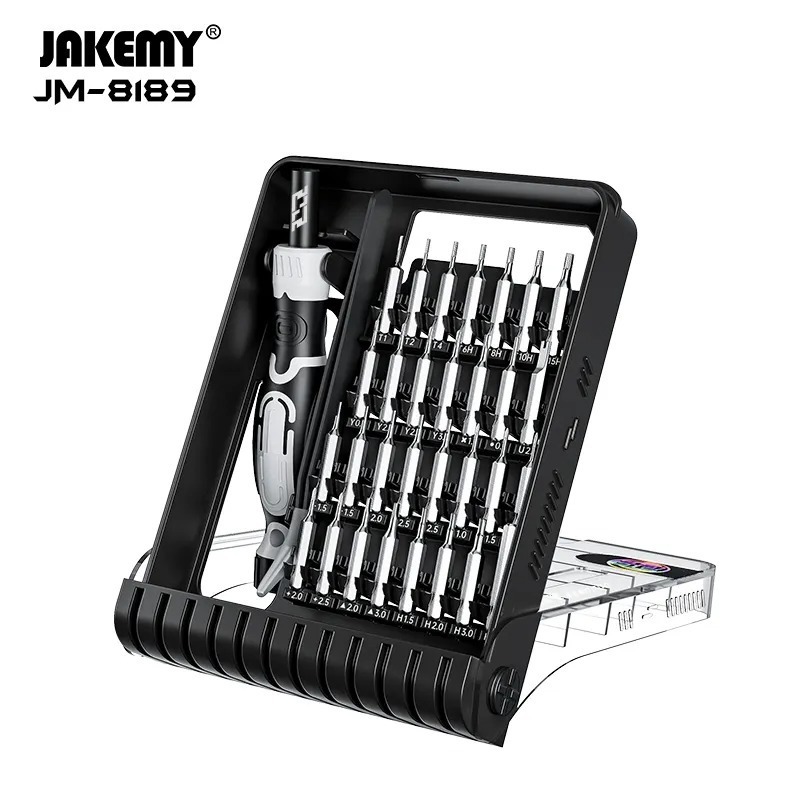
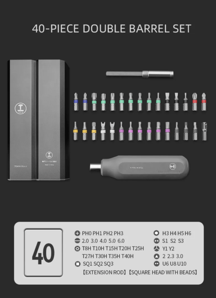
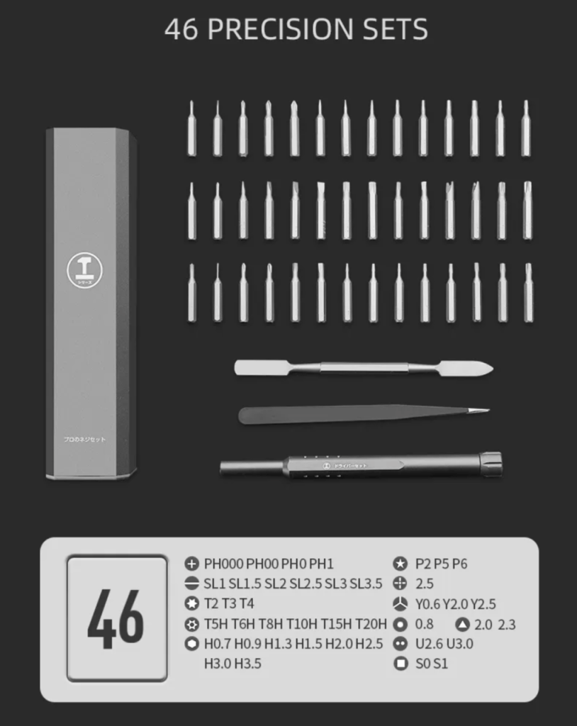
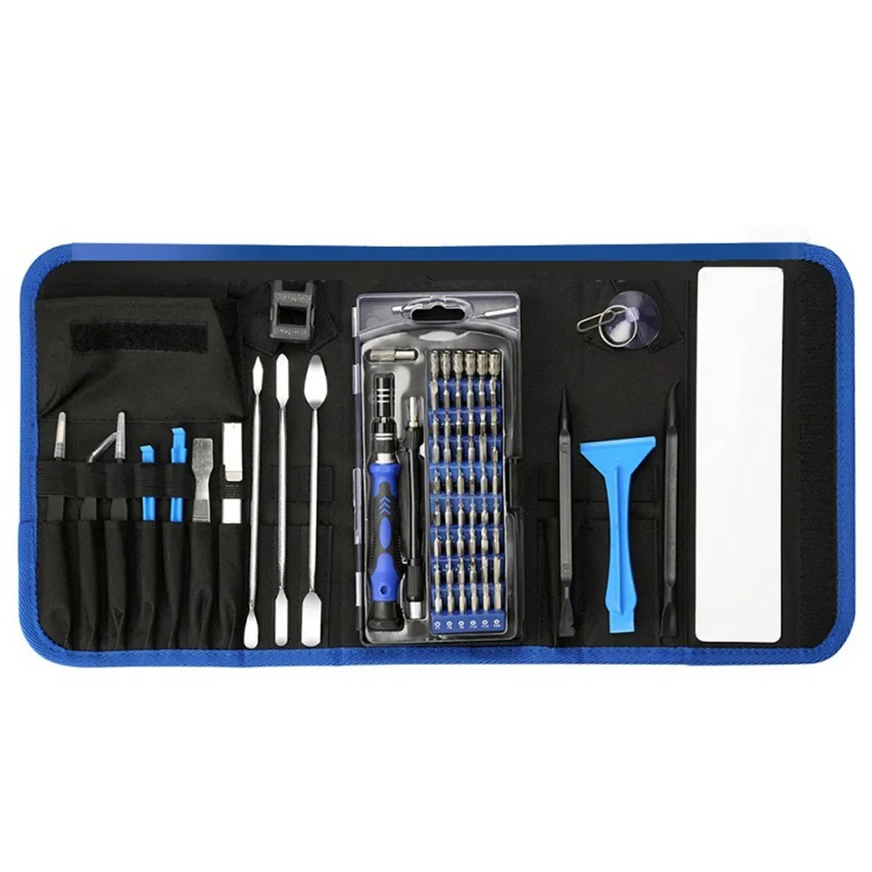
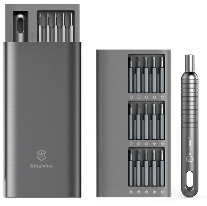
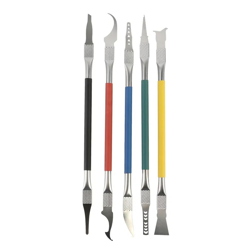
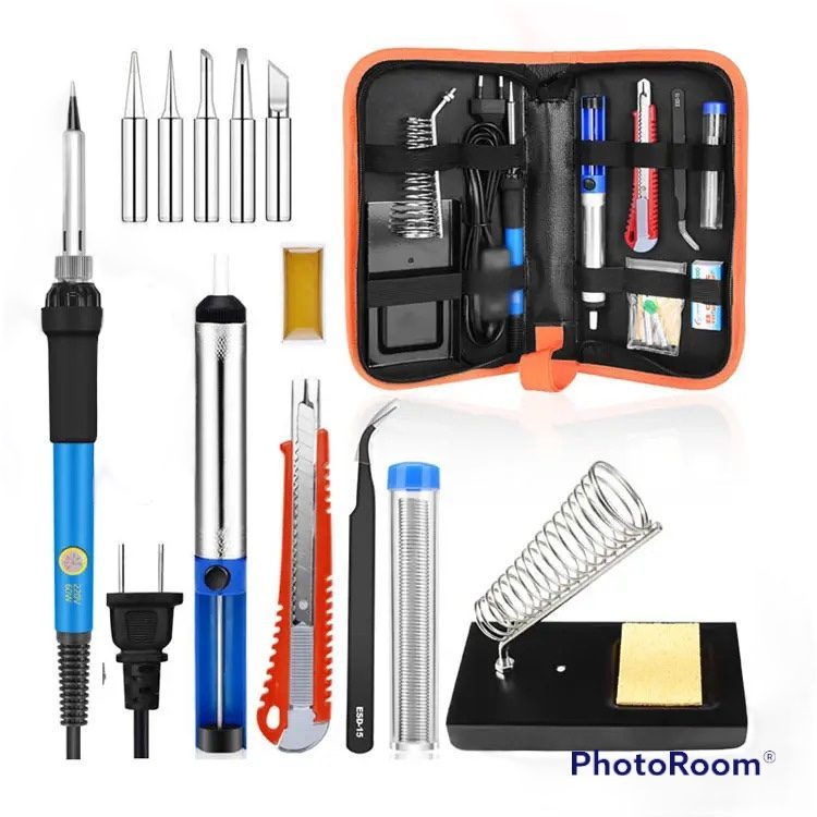
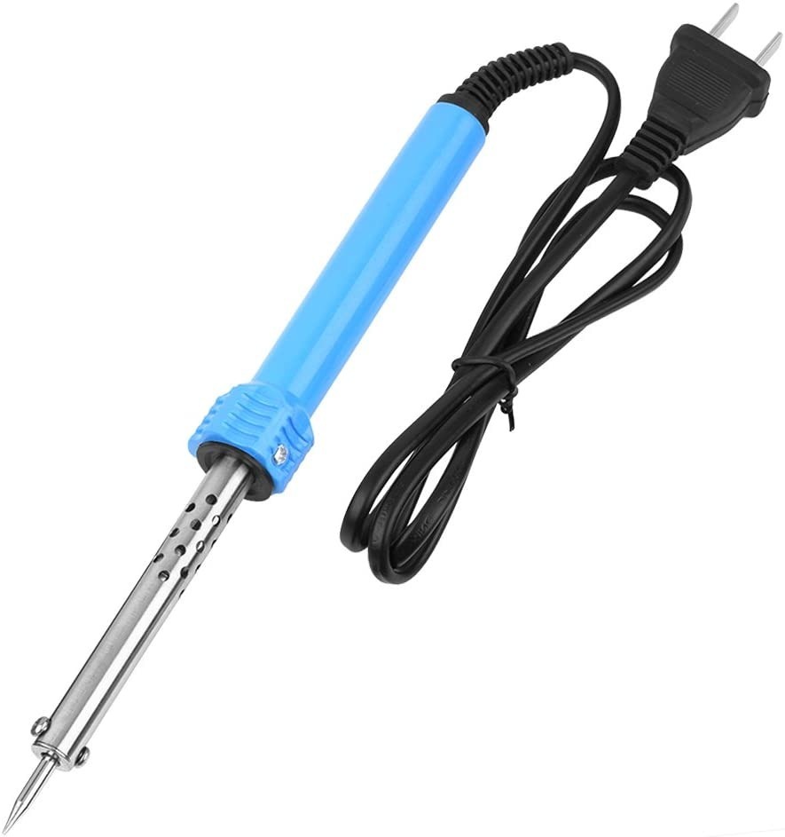
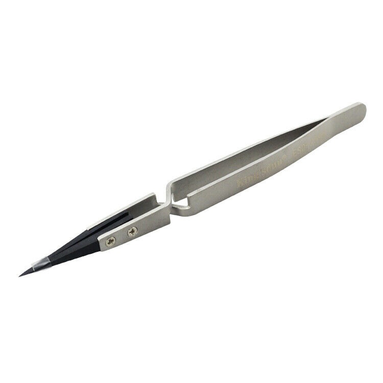
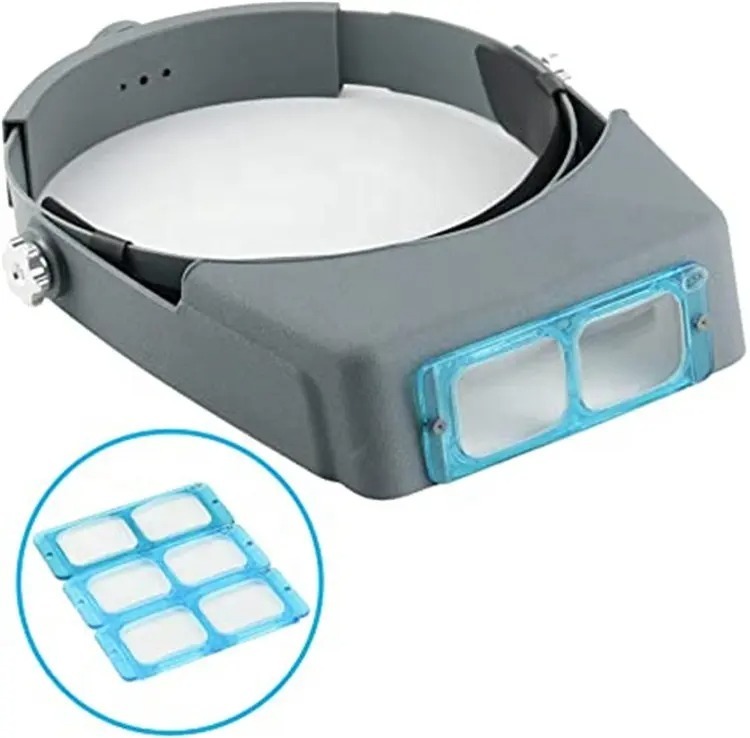
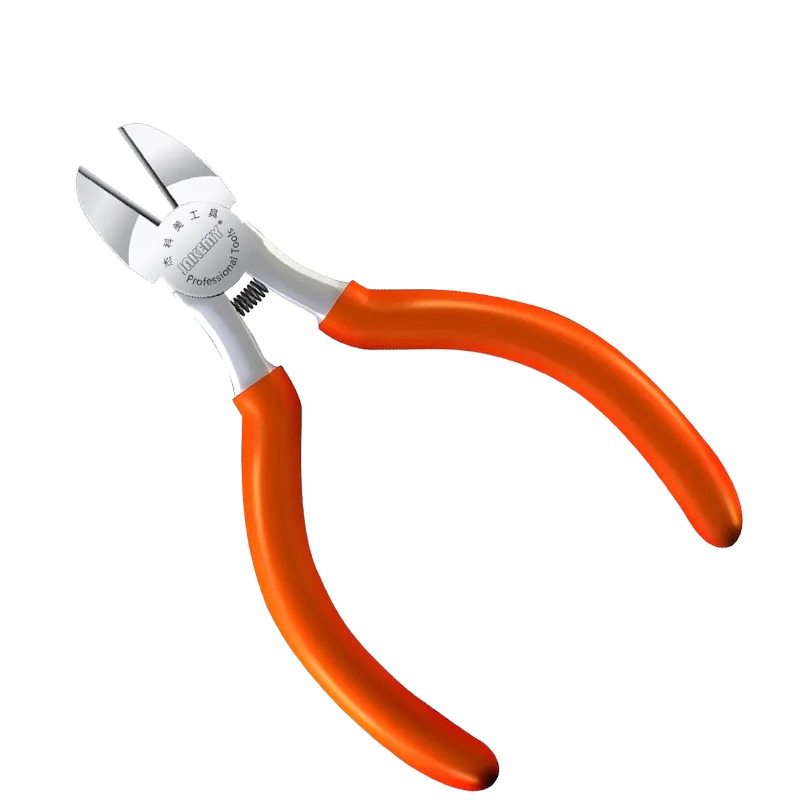
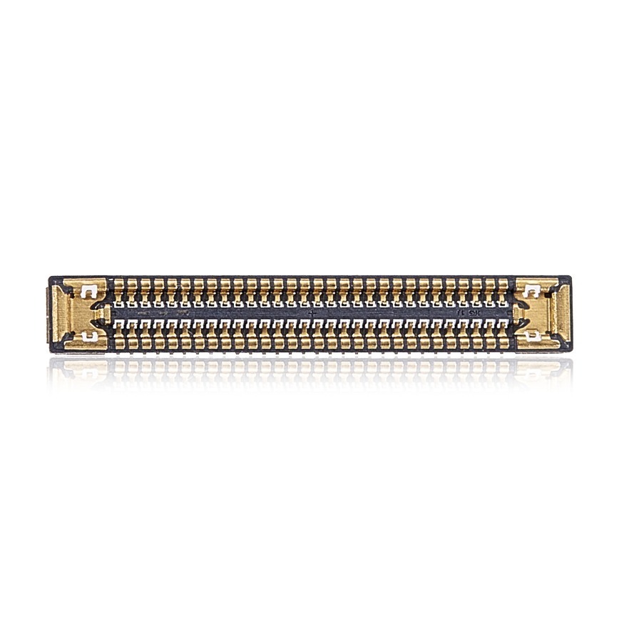
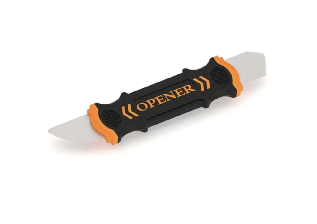
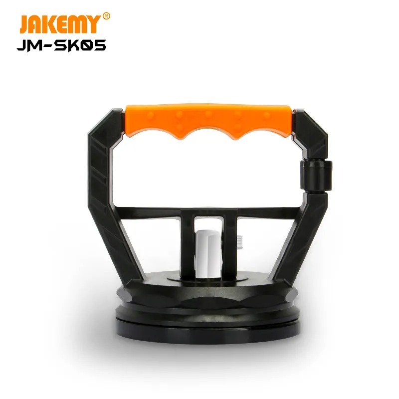
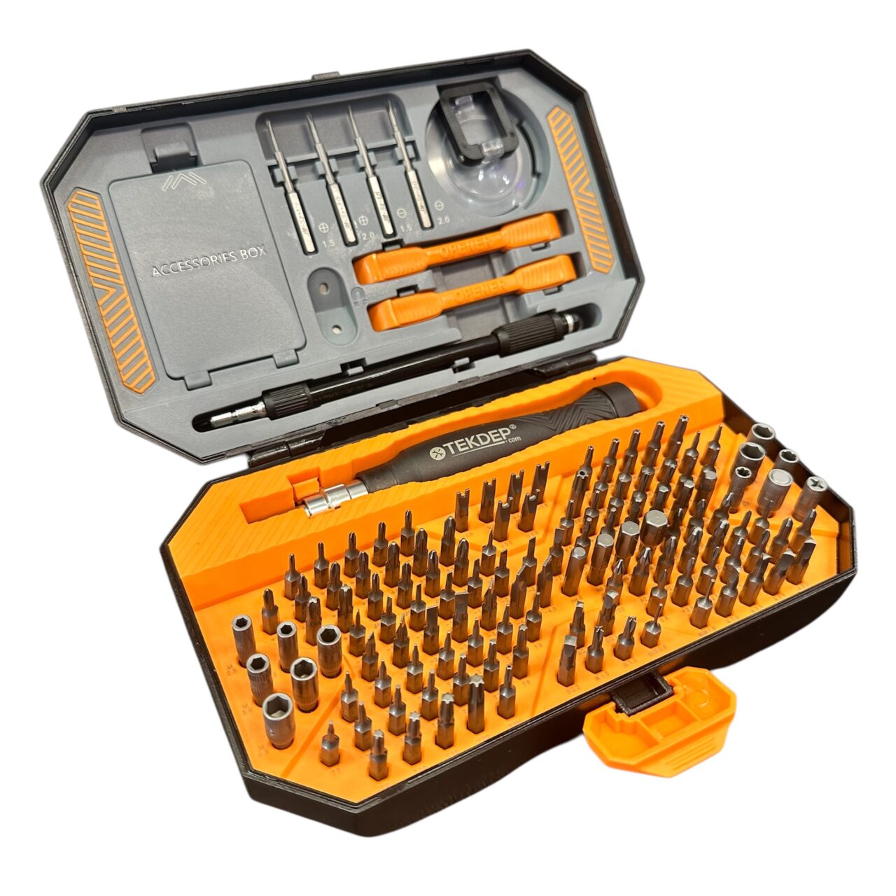
The A1706 requires a specific arsenal of tools. Stripping a logic board screw or using a conductive pry tool near the battery will instantly turn a repair into a replacement. Our specialized TEKDEP kits include everything you need for this exact teardown.
Required Tooling for the A1706:
- P5 Pentalobe Screwdriver: For the external backplate screws.
- Torx T3, T5, and T8 Screwdrivers: The core tools for the logic board, trackpad, and display hinges.
- Nylon Spudger & Anti-Static Pry Tools: Essential for safely disconnecting Lego-style and ZIF (Zero Insertion Force) flex cables.
- 99% Isopropyl Alcohol & Syringe: Crucial for safely dissolving battery adhesive.
Get the Professional Grade Tools Used by Our Techs:
Phase 1: Breaching the Chassis & Safe Disconnect
The journey begins by bypassing Apple’s external security and, crucially, killing the power to the highly sensitive logic board.
Step 1: Removing the Backplate
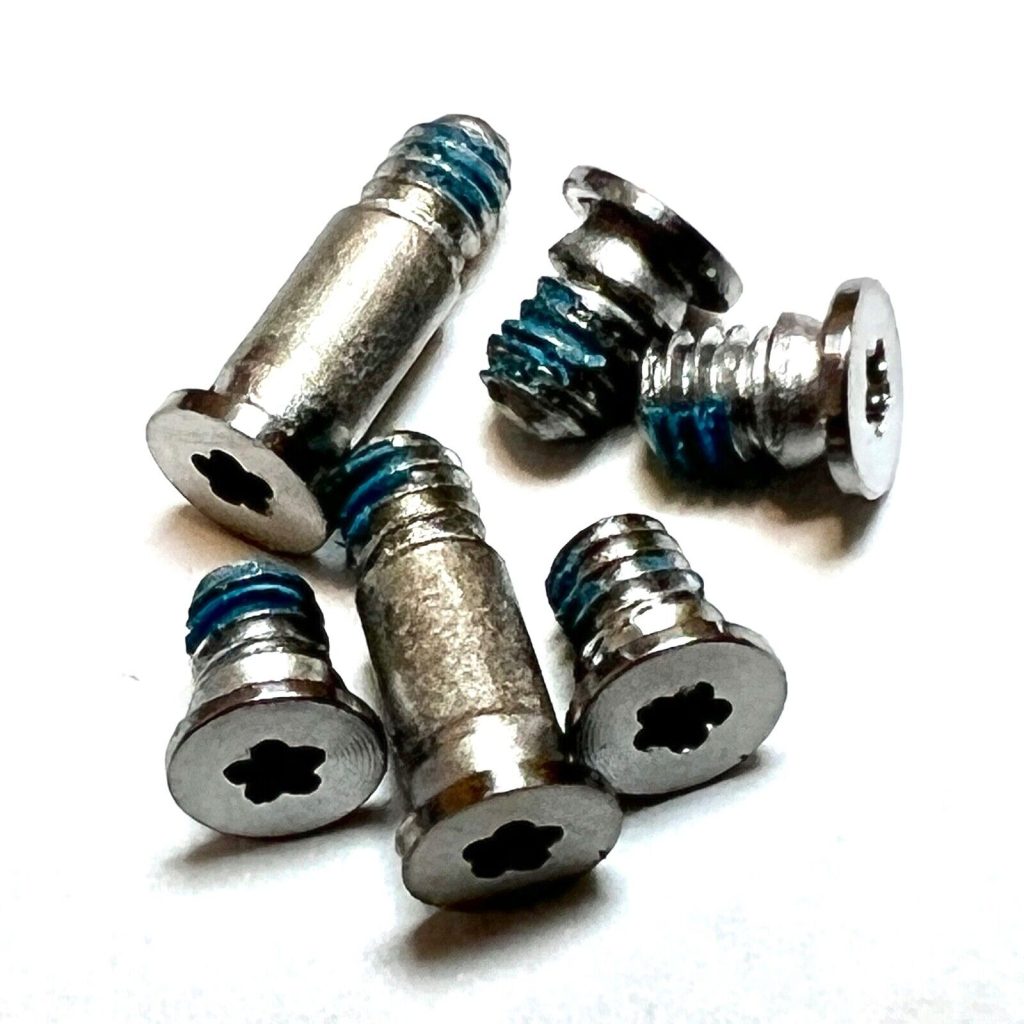
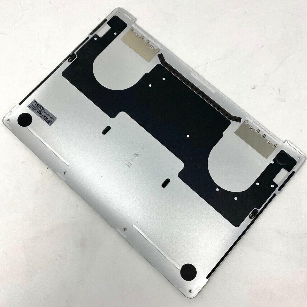
Turn the MacBook face down. Using your P5 Pentalobe screwdriver, remove the six screws securing the aluminum backplate. Once the screws are out, the plate won’t simply lift off. Insert a thin plastic pry tool into the side seams to release the internal clips. Once the sides pop free, place your hands flat on the backplate and slide it firmly downwards (away from the display hinges) to disengage the top hooks.


Step 2: Disconnecting the Battery (The Hidden Cable)
The A1706 features a hidden data cable that sits over the main battery power connector. First, locate the small data cable on the battery board. Flip up the tiny retaining latch and gently pull the cable straight back. Next, locate the large “pancake” screw beneath it. Use a T5 Torx driver to remove this screw. Lift the battery terminal away from the logic board contact pad.
Step 3: The 10-Second Capacitor Discharge
Disconnecting the battery is not enough. The logic board is loaded with surface-mounted capacitors that retain a deadly charge. Open the laptop slightly and press and hold the Power Button for 10 full seconds. This completely drains the capacitors, making the board electrically inert and safe for extraction.


Phase 2: The Trackpad & Haptic Feedback Mechanics
The massive Force Touch trackpad is relatively easy to remove, but requires careful handling of the delicate flex cable and specific calibration washers.
Step 1: Disconnecting the Trackpad Flex Cable
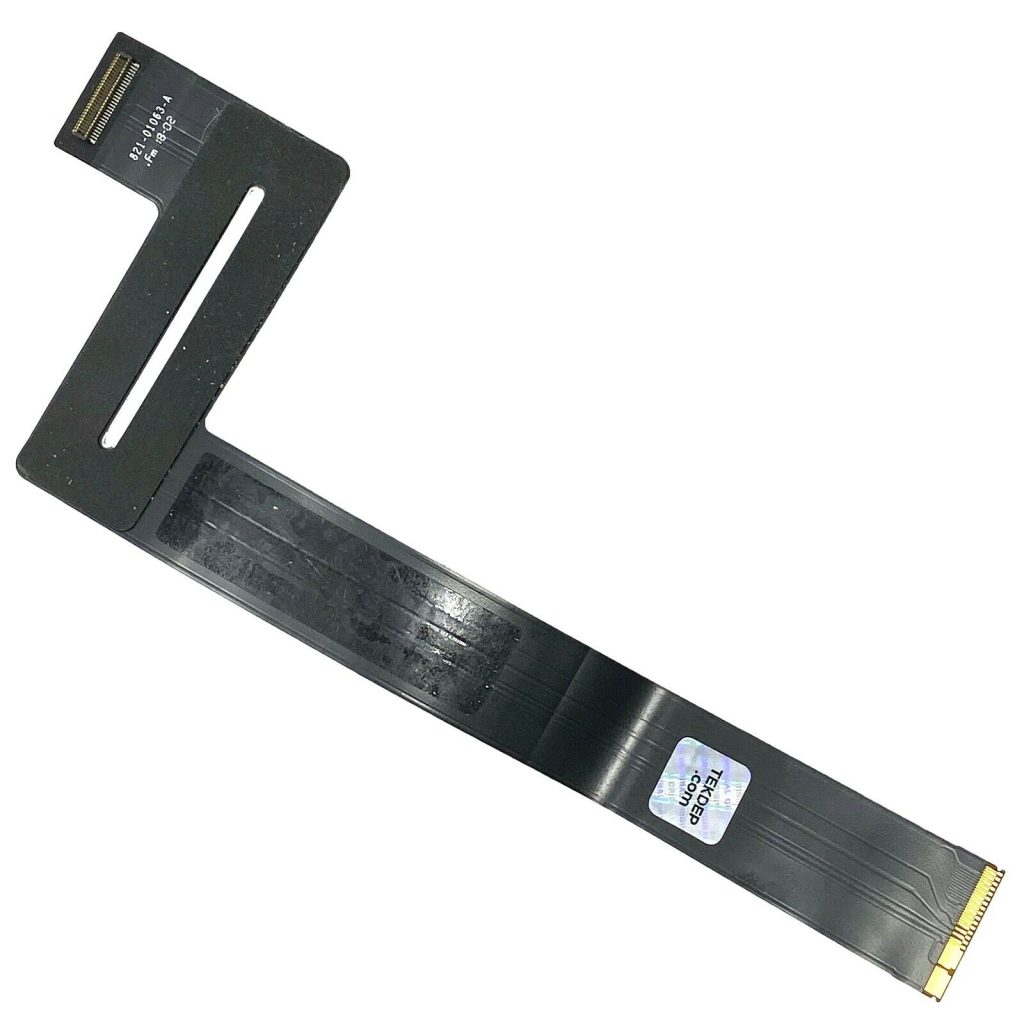
Locate the wide trackpad flex cable spanning the battery. Use a T3 screwdriver to remove the single screw holding the metal connector bracket to the logic board. Use a spudger to gently pop the connector up. Carefully peel the flex cable back, slicing through the mild adhesive holding it to the battery pouch.


Step 2: Trackpad Extraction
Use your T5 driver to remove the screws holding the metal trackpad brackets to the chassis. Once unscrewed, open the laptop slightly. The trackpad will drop out from the bottom.


Step 3: The Haptic Washers
When removing the trackpad, pay close attention to the tiny metal washers sitting on the screw posts. These are crucial for the Taptic Engine’s haptic feedback. If you lose them, your trackpad click will feel mushy or fail to register entirely.


Phase 3: The Brain (Logic Board & Touch ID Serialization)
Extracting the logic board provides access to the cooling fans, the USB-C ports, and the keyboard matrix. It is a dense maze of fragile flex cables and tiny T3 screws.
Step 1: Clearing the Peripheral Cables
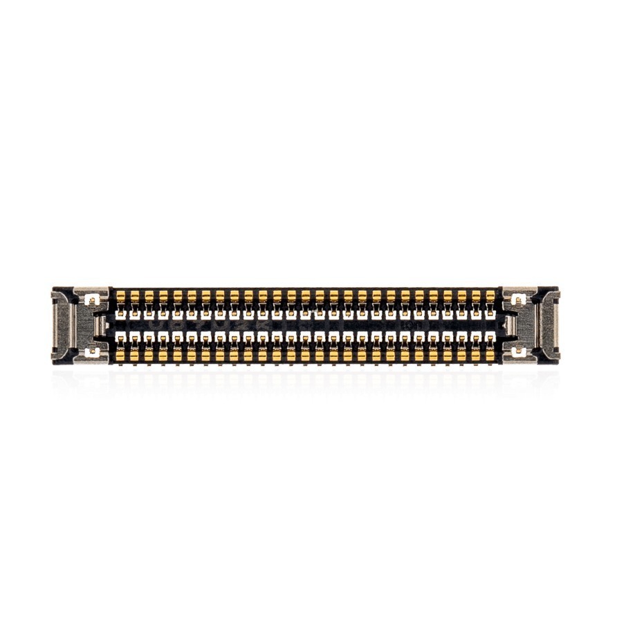
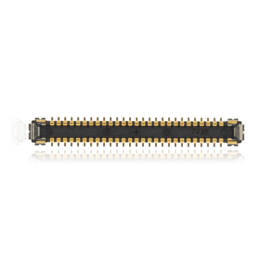
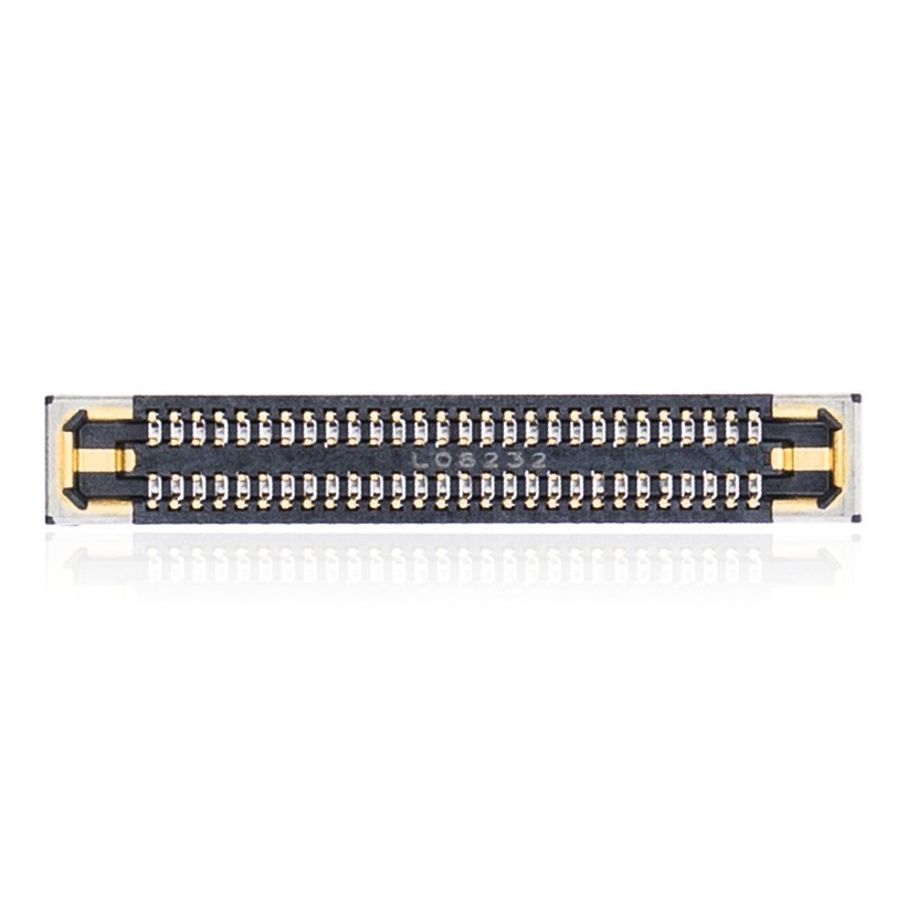
You must meticulously disconnect every flex cable bridging the logic board to the chassis. Use a nylon spudger to release:
- The display backlight and data cables.
- The Wi-Fi antenna cables.
- The dual cooling fan connectors.
- The Touch Bar data cables (extremely fragile).
- The Left and Right speaker connectors.
- The Audio jack connector.


Step 2: Logic Board Screws
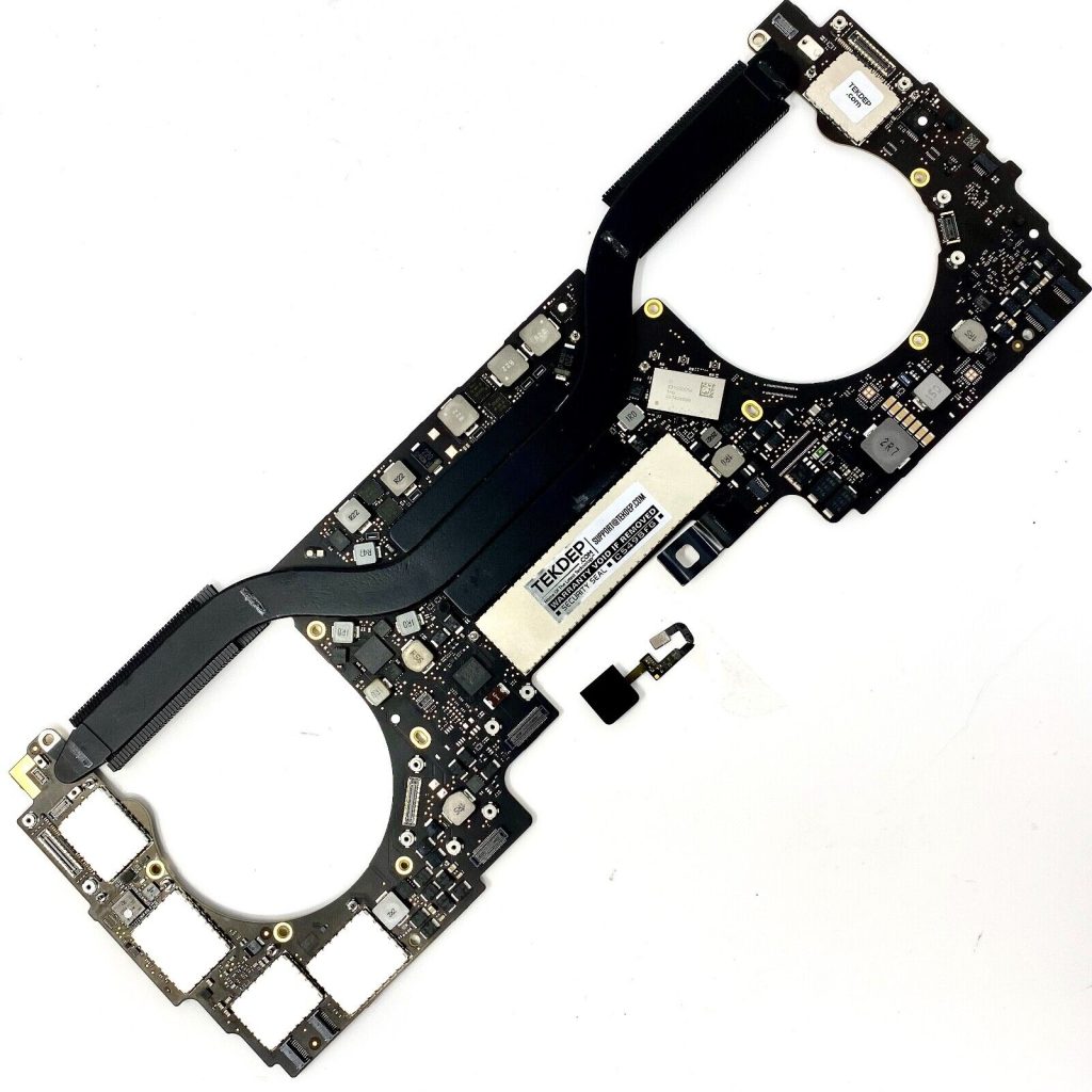
The logic board is secured by a series of T5 and T3 screws. Remove the larger T5 screws anchoring the heat sink and the main board sections, followed by the smaller T3 screws near the edges. Organization is critical here; document exactly where each screw originated.$$WP Gallery Location: Under Phase 3, Step 2$$

Step 3: Extraction and the Touch ID Warning
Once all screws and cables are free, gently lift the logic board starting from the side opposite the ports. Check underneath for any snagged cables before fully extracting it.
TekDep Expert Insight: “If you are replacing the logic board, you must remove the Touch ID sensor from the upper right corner of the chassis and transfer it to the new board. If you fail to do this, Touch ID will permanently cease to function, as the sensor is cryptographically serialized to the Secure Enclave on the original board.”


🛑 Intimidated by the Flex Cables and Glued Battery? The A1706 is infamous for being hostile to DIY repairs. One ripped Touch Bar cable or punctured battery cell can ruin the machine.
Let the TEKDEP experts handle the heavy lifting. We specialize in component-level A1706 repair.
Phase 4: High-Wear Peripherals (Fans, I/O, & Audio)
With the logic board removed, the modular, high-wear components are fully accessible.
Step 1: The USB-C I/O Boards
The dual USB-C/Thunderbolt ports are modular boards secured by two T5 screws. If a port is burnt out or physically damaged, simply unscrew the board and swap in a replacement.

Step 2: The Cooling Fans
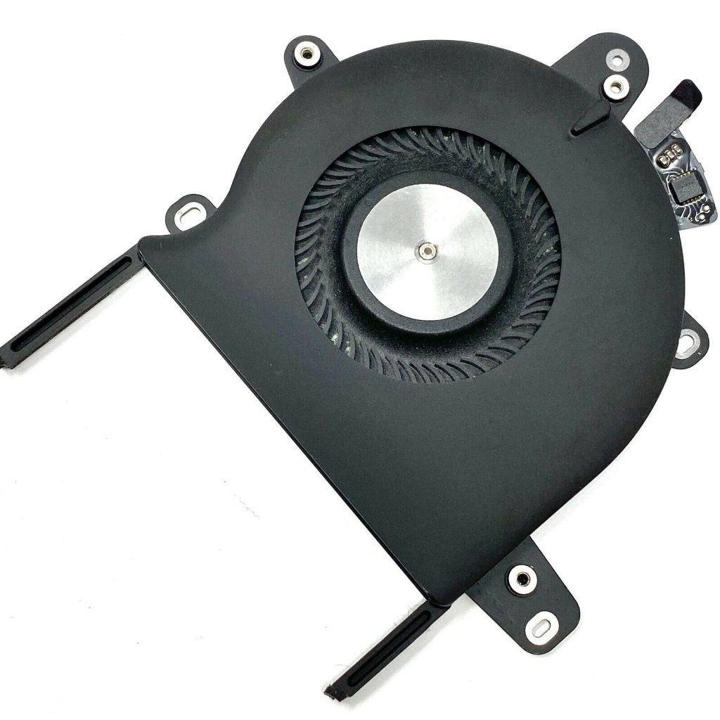
The dual cooling fans are held by a combination of T3 and T5 screws. Remove the screws, gently break the mild adhesive holding the fan housing, and lift them out. Regular cleaning of these fans is vital to prevent thermal throttling.

Step 3: The Audio Jack & Touch ID Sensor
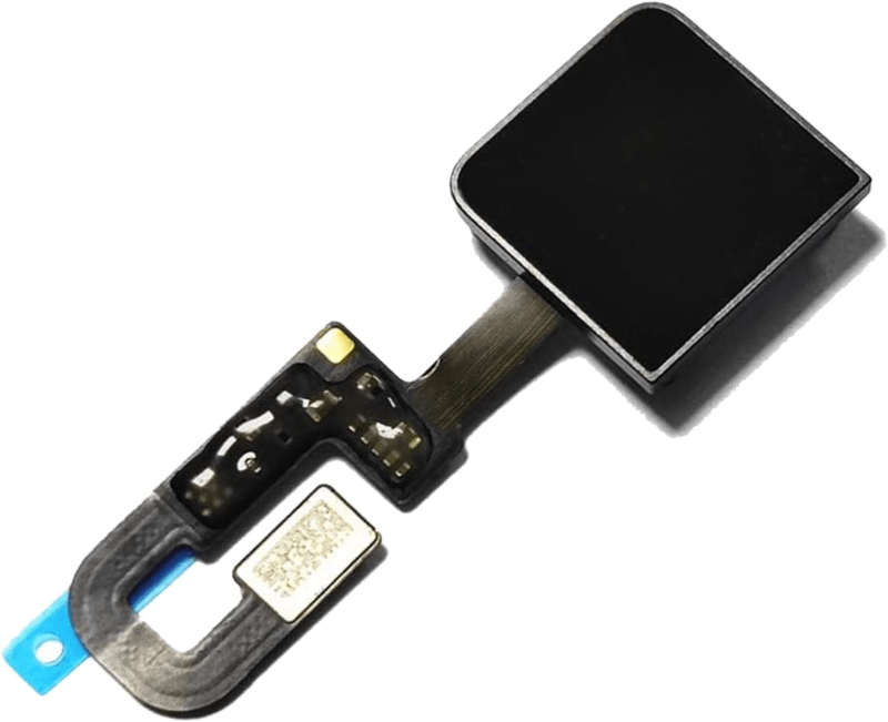
The audio jack is secured by T3 screws and can be easily swapped. The Touch ID sensor (power button) requires careful removal of its T3 retaining bracket. Gently slide the sensor out, being incredibly careful not to crease its fragile flex cable.



Phase 5: The Retina Display & Flexgate Diagnostic
The display assembly is the final major component to extract, and understanding how to handle it requires understanding the “Flexgate” flaw.
Step 1: The Wi-Fi Antenna Array
Use your Pentalobe driver to remove the tiny screws securing the Wi-Fi antenna bar located between the display hinges. Lift the antenna bar straight up and out.


Step 2: Display Hinge Screws
Switch to your T8 Torx driver. There are three large T8 screws securing each display hinge. Remove the outer two screws on each side first. Open the display to a 90-degree angle, then remove the final inner screws.


Step 3: Separating the Display
With the screws removed, carefully separate the upper display assembly from the lower chassis.

The Flexgate Reality: If you are performing this teardown because your screen goes black when opened past 45 degrees, you are a victim of Flexgate. The display flex cables are wrapped too tightly around the controller board. Over time, the tension causes the internal copper traces to fracture. Because Apple integrated these cables directly into the display panel, you cannot simply replace the cable; you must replace the entire Retina Display assembly.
Comparing the A1706 (2016-2017) to the 2018-2019 Models
If you are dealing with a 13-inch MacBook Pro from this era, it is critical to understand the slight variations between models, as parts are rarely cross-compatible. As heavily documented across Apple Support Communities regarding A1706 power and keyboard issues, accurately identifying your model year dictates the repair path.
- A1706 (Late 2016 – Mid 2017): Features the original, highly problematic 1st and 2nd generation Butterfly keyboard and the shorter display flex cables prone to the “Flexgate” issue.
- A1989 (Mid 2018 – Mid 2019): Apple introduced the 3rd generation Butterfly keyboard (adding a silicone membrane to mitigate dust) and slightly lengthened the display flex cables to quietly address the Flexgate flaw. The battery capacity also slightly increased, meaning A1706 and A1989 batteries are not interchangeable.
- A2159 (Mid 2019): Continued the refinement of the 3rd Gen Butterfly keyboard and featured updated internal thermal management.
While the teardown process for the A1989 and A2159 is virtually identical to this A1706 guide, the specific part numbers for batteries, logic boards, and displays are strictly unique to their respective model years.
Still trying to decide if the financial investment is worth it?
Read our comprehensive analysis: Is It Cheaper to Repair or Replace a Computer?
TEKDEP is your professional safety net. Our cleanroom-equipped lab specializes in advanced micro-soldering, Flexgate display swaps, and safe battery extractions for the entire MacBook Pro lineup.
Frequently Asked Questions (FAQ)
What is the Flexgate issue on the A1706?
The Flexgate issue on the A1706 (Late 2016 to Mid 2017) refers to a design flaw where the display flex cables are too short. Opening and closing the lid repeatedly causes these cables to tear, leading to a ‘stage light’ effect or a completely black screen. The only fix is a full display assembly replacement.
How hard is it to replace the battery in the MacBook Pro A1706?
Replacing the A1706 battery is notoriously difficult because Apple heavily glued the lithium-ion cells to the upper chassis. It requires careful application of 99% isopropyl alcohol and non-marring tools to dissolve the adhesive without puncturing the highly volatile cells.
Can I upgrade the RAM or SSD in the MacBook Pro A1706?
No. The MacBook Pro A1706 features a highly integrated logic board where both the RAM and the SSD are soldered directly to the motherboard. To upgrade storage or memory, you must replace the entire logic board.
The A1706 Legacy and Repair Realities
The MacBook Pro A1706 represents a pivotal, highly controversial shift in Apple’s design history. By prioritizing extreme thinness and introducing the OLED Touch Bar, Apple created a machine that is visually stunning but inherently hostile to DIY repair. From the aggressively glued lithium-ion batteries to the unforgiving Flexgate display cables, successfully tearing down and rebuilding an A1706 is a true test of a technician’s skill and patience.
While mastering this teardown is a rewarding rite of passage for dedicated fixers, the margin for error is razor-thin. If you have popped the backplate off your A1706 and feel overwhelmed by the dense maze of microscopic T3 screws and fragile ZIF connectors, do not risk further damage to your logic board.
🛑 IMPORTANT: SAFETY & LIABILITY DISCLAIMER TEKDEP®️ TEKDEP.com assumes no liability for property damage or injury incurred as a result of any information in this blog post or associated videos. Dealing with internal computer components, specifically glued Lithium-Ion Polymer batteries, carries inherent risks including fire, toxic gas exposure, and irreversible device failure. Any injury, damage, or loss from improper use of tools, mishandling of components, or misinterpretation of this information is the sole responsibility of the user. Perform repairs at your own risk. If you are unsure of your capabilities, please utilize our professional Mail-In Repair Service.